Some Known Incorrect Statements About Wedge Barriers
Wiki Article
Getting The Wedge Barriers To Work
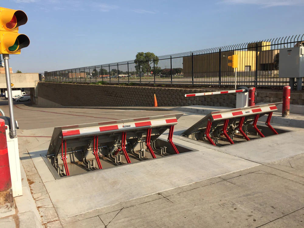
14 and the surface 12 to which the obstacle 10 is protected may be made from concrete - Wedge Barriers. 2, the barrier 10 is mounted to or consists of an anchor or subframe (e. g., support 30 received FIG. 2 )secured beneath the surface area 12. As an example, the bather 10 may be bolted to the anchor or safeguarded to the anchor by various other mechanical bolts. In the detailed personification, the barrier 10 consists of a wedge plate 16, that includes a section that is significantly identical with the surface area 12 when the obstacle 10 remains in the retracted placement. Simply put, lorries or people might overlook the barrier 10 when the obstacle 10 is in the retracted setting and experience slight elevation about the surface 12 while on the barrier 10. As discussed carefully listed below, when the barrier 10 remains in the deployed position, the wedge plate 16 is held and sustained in an elevated placement by a training system of the barrier 10. Additionally, the components 18 may be bolted or otherwise mechanically coupled to each other. In this way, fixing or substitute of several elements 18 may be streamlined and structured. That is, repair work or replacement of single elements 18 may be done quicker, quickly, and expense effectively. FIG. In particular embodiments, the anchor 30 may be a steel structure including plates, beams(e. g., I-beams ), and/or other frameworks that are secured within the structure 14, which might be concrete. At the surface 12, a top side 28 of the support 30 may be at least partly revealed , thus making it possible for the accessory of the barrier 10 to the support 30. g., threaded openings)in several beam of lights or plates of the anchor 30 might be exposed to the surface 12. In this way, bolts 32 or other mechanical bolts might be made use of to secure the barrier 10 to the anchor 30. As the obstacle 10 is placed to the surface 12 of the foundation 14, collection of debris and various other material under the barrier might be reduced, and parts of the bather 10 might not be exposed to below grade atmospheres. As indicated by referral character 52, the training device 50 consists of components disposed below the wedge plate 16. The elements 52 below the wedge plate 16 may include an electromechanical actuator, a cam, one or more camera surfaces, click reference and so forth. In addition, the training device 50 includes a springtime assembly 54
The springtime pole 58 is paired to a camera(e. g., cam 80 received FIG. 4) of the training system 50. The springtimes 60 disposed concerning the spring pole 58 are kept in compression by spring sustains 62, consisting of a fixed spring support 64. That is, the fixed spring support 64 a knockout post is dealt with family member to the foundation 14 and the remainder of the bather 10.
The Ultimate Guide To Wedge Barriers
g., spring assistance 65 )may be fixed to the end of the springtime pole 58 to make it possible for compression of the springtimes 60. As the springtimes 60 are compressed between the spring supports 62, the springtime setting up 54 creates a force acting on the webcam coupled to the springtime rod 58 in a direction 66. The continuing to be pressure used to the cam web cam deploy the wedge plate 16 may be provided offered an electromechanical actuator 84 or other various other. Because of this, the spring setting up 54 and the actuator 84(e. g., electromechanical actuator)may operate together to translate the cam and lift the wedge plate 16.
As discussed above, in the deployed placement, the wedge plate 16 offers to block access or traveling past the obstacle 10. The barrier 10(e. g., the wedge plate 16 )might obstruct pedestrians or cars site here from accessing a home or pathway. If a car is traveling in the direction of the deployed wedge plate 16(e. For instance, in one situation, the safety legs 86 may be extended throughoutmaintenance of the barrier 10.
Report this wiki page